Amplifier Distortion in Wireless Communication Systems
In wireless communication systems, RF impairments refer to factors that affect signal transmission quality, such as noise, nonlinear distortion, or frequency interference. Other than the thermal noise, a more comprehensible RF impairment is amplifier distortion.
Amplifiers are critical components in the wireless transmitters and receivers. Positioned close to the antenna, their primary role is to amplify input signals to higher power levels while maintaining linearity. However, achieving both high power and linearity often involves trade-offs.
Common Types of Amplifier Distortion
- Amplitude Distortion: When input power increases, the output signal’s amplitude is clipped or compressed.
- Phase Distortion: Nonlinearities introduce phase shifts, altering the signal’s phase information (will not be discussed here).
- Intermodulation Distortion (IMD): When multiple signals of different frequencies are input to an amplifier, its nonlinear characteristics cause these signals to mix, producing new frequency components.
Amplitude Distortion
In an amplifier’s linear operating region, output power is proportional to input power and can be expressed as: Output Power = Input Power + Gain (on a dB scale). However, as input power continues to increase, the output deviates from this linear relationship and approaches a saturation limit, leading to amplitude distortion.
A key parameter here is the 1 dB compression point (P1dB), which defines the input power level at which the output power is 1 dB below the theoretical linear output. This marks the boundary between the linear and nonlinear operating regions.

Amplitude compression and P1dB (from everythingrf.com)
Why is P1dB important? In applications where the linearity is critical, signal power must remain below P1dB (typically 3-5 dB lower) to avoid significant distortion and maintain signal quality.
Example: Amplifying a QAM signal beyond the linear region compresses the outermost constellation points, leading to distortion and degraded performance.

Amplitude Distortion for a QAM Signal (from Matlab Documentation)
Why Operate Amplifiers in the Nonlinear Region?
While operating in the linear region ensures signal integrity, it limits output power, making it inadequate for high-power signal transmission. To extend range or meet higher power requirements, amplifiers often operate in the nonlinear region. This trade-off balances output power and signal distortion, particularly in long-distance wireless systems.
Mitigating Amplitude Distortion
To address the signal quality issues caused by nonlinear distortion, Digital Predistortion (DPD) is a widely used technique.
Principle of Digital Predistortion:
- Measure the amplifier’s nonlinear characteristics to create a distortion model.
- Design an inverse filter to preprocess the input signal, introducing distortion opposite to the amplifier’s characteristics.
- After amplification, the preprocessed “distortion” cancels out the amplifier’s nonlinear distortion, restoring signal linearity.
In simple terms, the input signal undergoes “predistortion” before amplification, ultimately compensating for the nonlinear effects. However, DPD is effective only when the amplifier operates within its non-saturated region and cannot extend the amplifier’s linear range indefinitely.
Intermodulation Distortion (IMD)
Harmonics and intermodulation are common forms of amplifier distortion, often occurring in nonlinear operating conditions. While amplifiers are primary sources, other nonlinear components can also generate these distortions.
Harmonics
Harmonics are frequency components at integer multiples of the fundamental signal frequency, e.g., $2f, 3f, 4f$, etc. Their amplitudes decrease with increasing order.
Intermodulation
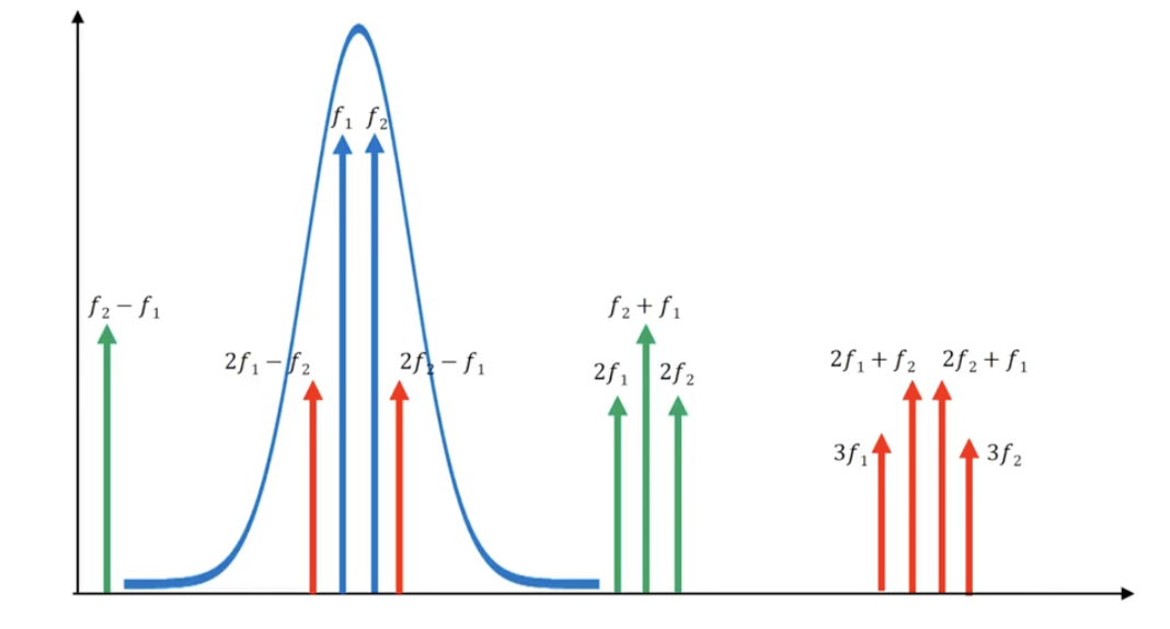
When two closely spaced single-frequency signals are present, their harmonics and fundamentals interact, producing intermodulation products. If the fundamental frequencies are $f_1$ and $f_2$, possible intermodulation frequencies include:
- Second-Order Products: $f_1 + f_2$, $f_1 - f_2$.
- Third-Order Products: $2f_1 + f_2, 2f_1 - f_2, f_1 + 2f_2, -f_1 + 2f_2$.
Special attention is given to $2f_1 - f_2$ and $2f_2 - f_1$ due to their:
- Higher amplitudes at lower orders.
- Proximity to the original signal frequencies, making them difficult to filter.
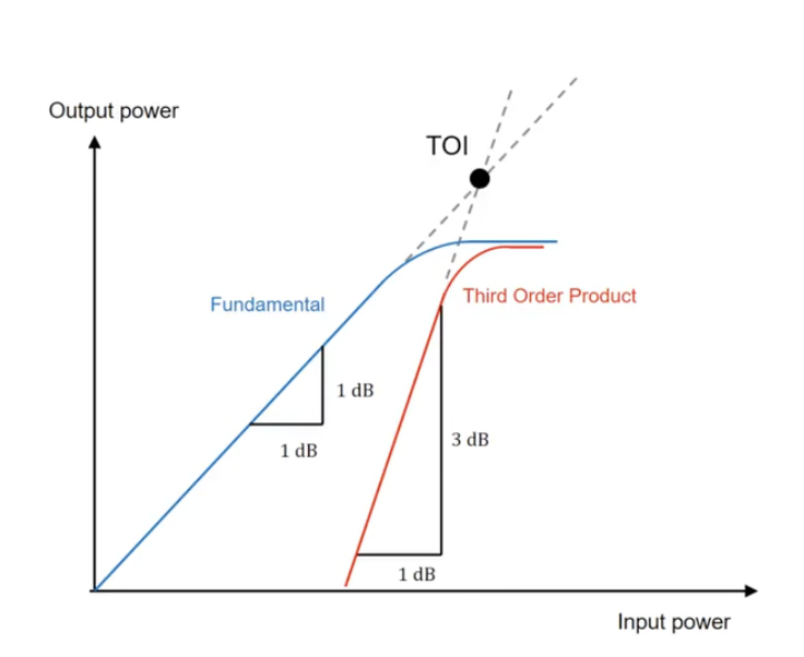
- Increase in power by 3 dB for every 1 dB increase in input power.

Intermodulation and third-order products (from Rohde & Schwarz)
Third-order intermodulation distortion (IMD) is particularly significant. Assuming the RF device does not saturate, the point at which third-order intermodulation power equals the fundamental output power is the third-order intercept point (IP3 or IIP3). Though this point is theoretical due to compression effects, it serves as a key linearity metric. Higher IP3 values indicate better linearity and lower IMD.

the IP3 point (from Rohde & Schwarz)
IP3 Measurement
I found an very useful YouTube video that explains Third Order Intercept and how to measure it.


IP3 Measurements (from Rohde & Schwarz)
Conclusion
Amplifier distortion is a critical consideration in wireless communication systems. While operating in the nonlinear region enables higher power outputs, it introduces signal distortion that degrades transmission quality. Key nonlinear effects include amplitude distortion, phase distortion, and intermodulation distortion, with intermodulation being particularly impactful due to the generation of additional frequency components within the operational band.
By employing techniques like DPD and evaluating linearity metrics such as P1dB and IP3, designers can optimize amplifier performance, achieving a balance between efficiency and linearity. Striking this balance is essential for delivering reliable and high-quality communication.
Comments powered by Disqus.