Understanding Zero-IF Transceivers and DC Offset
Introduction
Zero-IF transceivers, also known as direct conversion transceivers, are widely used due to their simplicity and low cost. These attributes make them particularly suitable for applications where minimizing hardware complexity and expense is crucial, such as in consumer electronics and portable communication devices. However, they introduce several impairments, including DC offset and IQ imbalance. This article reviews their architecture and focuses on the DC offset impairment. The IQ imbalance will be addressed in a subsequent article.
Direct Conversion Receivers
Zero-IF transceivers are also referred to as direct conversion transceivers because they directly convert the RF signal to baseband without using an intermediate frequency (IF) stage.
To understand the causes of DC offset and IQ imbalance, it is essential to examine the architecture, as it provides critical insights into how these impairments originate and propagate through the signal processing chain.
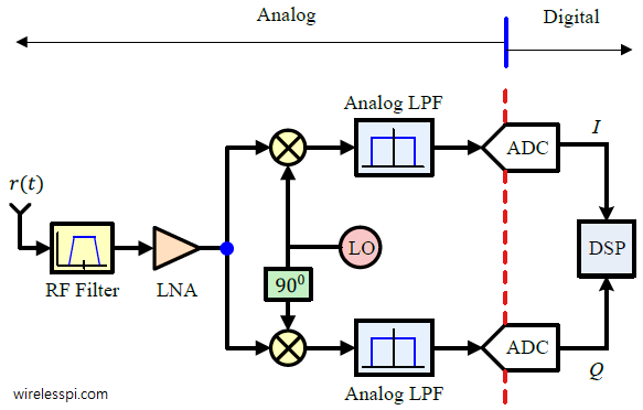
The block diagram of a zero-IF receiver (the transmitter has a similar but reversed diagram) is shown below:

block diagram of a zero-IF receiver from wirelesspi.com
The analog potion of the zero-IF receiver consists of a preselection filter, low noise amplifier (LNA), mixers, and lowpass filters (LPFs).
Preselection Filter
The preselection filter might appear unnecessary at first glance, but it is essential to filter out unwanted signals, prevent out-of-band interference, and improve the receiver’s performance.
Without the preselection filter (such as in some USRPs), the receiver may become saturated by strong out-of-band signals. Combined with the odd-order harmonics from the local oscillator (LO), the receiver may inadvertently pick up undesired signals.
Low Noise Amplifier (LNA)
The LNA amplifies the power of the received RF signal. Note the following points:
- The LNA does not increase the signal-to-noise ratio (SNR) of the received signal; it amplifies both the signal and noise, slightly degrading the SNR.
- Despite this, the LNA is necessary because the received signal may be too weak and could be overwhelmed by noise introduced in subsequent stages.
- The LNA ensures that the signal of interest maintains sufficient power for processing by the ADC, such that it is neither too weak to detect nor too strong to saturate the ADC. This mechanism is called automatic gain control (AGC).
- As the first stage, the LNA’s noise figure is crucial to the receiver’s overall noise performance. This is why a low-noise amplifier is required. Check out the previous article for more details.
- The counterpart of the LNA in the transmitter is the power amplifier (PA), which amplifies the signal power before transmission. The PA’s nonlinearity was discussed in this article.
Mixers and LPFs
The mixers downconvert the RF signal to baseband by multiplying the RF signal with quadrature sinusoids.
The two sinusoids are generated by the LO, ensuring they are identical in amplitude and have a 90-degree phase difference.
The mixers’ output comprises the in-phase (I) and quadrature (Q) components of the baseband signal. The LPFs filter out high-frequency components, leaving only the desired baseband signal.
DC Offset
The spectrum of the IQ output of the ADC often includes a strong DC component, known as the DC offset.
This impairment is caused by LO leakage in the mixers. LO leakage occurs when a portion of the LO signal inadvertently leaks into the RF input path, leading to interference. This leakage creates a zero-frequency component in the IQ output, manifesting as DC offset.
DC offset is particularly problematic for single-carrier systems, such as QPSK, because it can shift constellation points, leading to errors in the demodulation process. For OFDM systems, the DC offset can often be mitigated by nulling out the DC carrier in the transmitted waveform. For instance, Wi-Fi systems null the DC carrier in OFDM waveforms.
Many transceivers include DC offset cancellation circuits to mitigate this impairment. These circuits estimate the DC offset and subtract it from the IQ output or apply a filter to suppress the DC component. However, DC offset cancellation is not perfect and may introduce additional noise or impairments.
Conclusion
In this article, we explored the architecture of zero-IF transceivers and the DC offset impairment. In the next article, we will examine the IQ imbalance impairment and its impact on wireless communication systems.
Comments powered by Disqus.