Understanding IQ Imbalance
Introduction
In the previous article, we discussed the architecture of zero-IF transceivers and the DC offset impairment. This article will dive into another significant impairment closely related to the zero-IF transceiver architecture: IQ imbalance.
IQ Imbalance
When working with the USRP, I frequently encountered an issue: an image signal at the opposite frequency of the original signal, degrading the overall capture quality.
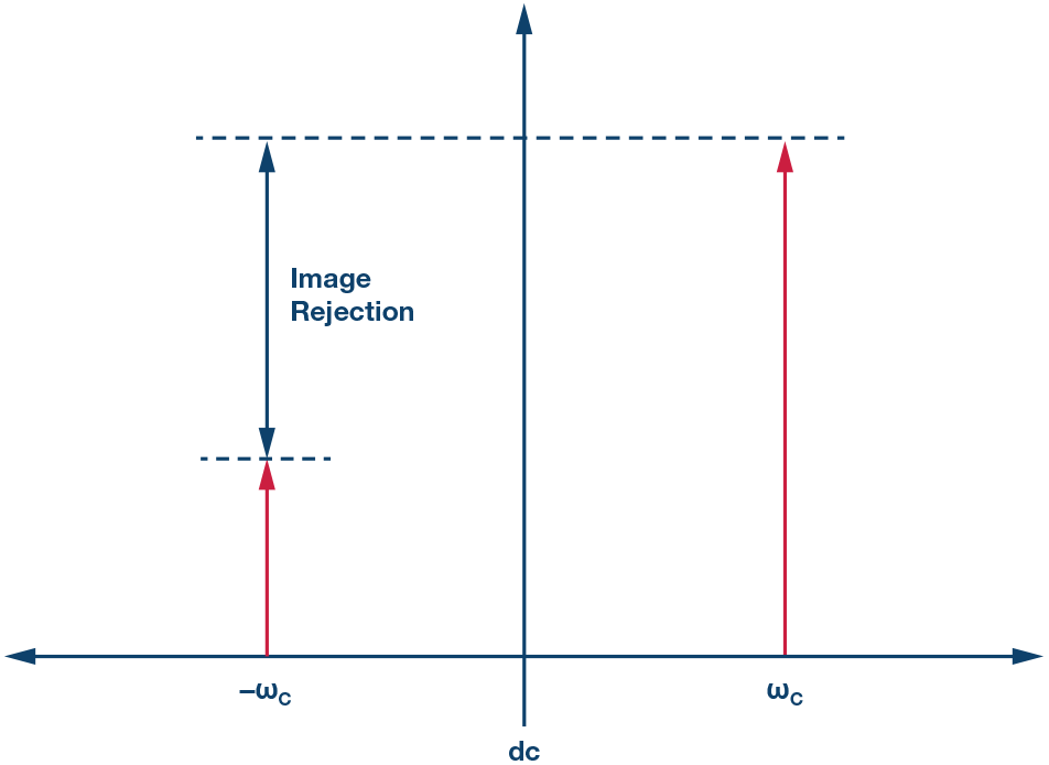
For instance, if a sine wave is received at the frequency $f_c$, there is always an unwanted sine wave at $-f_c$. Although generally weaker in power compared to the main signal, it is still a major distortion for many zero-IF transceivers. This phenomenon is caused by IQ imbalance.

Image signal due to IQ imbalance (from Matlab documentation)
This issue may not seem intuitive. How does IQ imbalance generate an image signal? And more importantly, what exactly is IQ imbalance?
Causes of IQ Imbalance
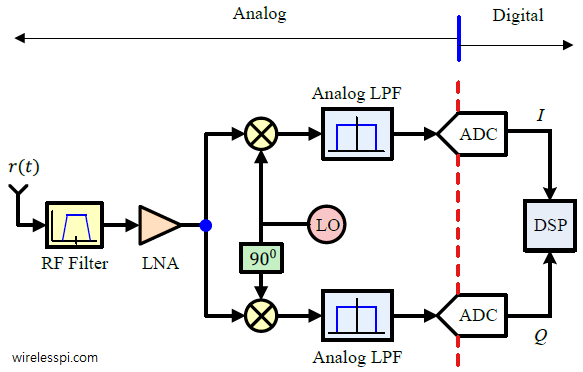
Let’s review the architecture of a zero-IF receiver, as shown below:

Block diagram of a zero-IF receiver (from wirelesspi.com)
In the last article, we mentioned the following:
- The mixers downconvert the RF signal to baseband by multiplying it with quadrature sine waves.
- The two sine waves are generated by the LO, ensuring identical amplitude and a 90-degree phase difference.
- The mixers’ output comprises the in-phase (I) and quadrature (Q) components of the baseband signal. The LPFs filter out high-frequency components, leaving only the desired baseband signal.
However, analog components cannot perfectly generate two sine waves with identical amplitude and phase, leading to IQ imbalance impairment.
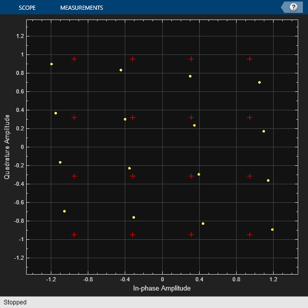
For example, a 16-QAM signal affected by IQ imbalance can be visualized as follows:

Distorted constellation due to IQ imbalance (image from Matlab documentation)
Here, the red crosses represent the ideal constellation points, while the yellow dots represent the distorted points caused by IQ imbalance.
So far, the distortion in the constellation is relatively intuitive, but why is there an image signal? One way to understand it is by visualizing the sine wave as a rotating vector in the complex (IQ) plane. Without IQ imbalance, the trace forms a perfect circle. However, with IQ imbalance, the trace becomes an oval, which can be decomposed into two rotating circles with the same freuqency but opposite directions and different radii. The circle with the smaller radius represents the image signal. While the exact proof is omitted here, this provides an intuitive understanding of the image signal.
Mathematical Model
Let’s model the IQ imbalance impairment mathematically. The LO’s output in the I and Q branches can be expressed as $cos(w_c t)$ and $-sin(w_c t)$, respectively. By applying a phase difference $\phi$ and a gain difference $g$ to the Q branch, the overall LO output becomes:
\[a(t) = \cos(\omega_c t) - jg \sin(\omega_c t + \phi)\]where $j$ is the imaginary unit. Using Euler’s formula, this equation can be rewritten as:
\[a(t) = \left( \frac{1 + g e^{-j \phi}}{2} \right) e^{-j \omega_c t} + \left( \frac{1 - g e^{j \phi}}{2} \right) e^{j \omega_c t}\]Then we collect the coefficients of $e^{-j \omega_c t}$ and $e^{j \omega_c t}$, we have
\[a(t) = \left( \frac{1 + g e^{-j \phi}}{2} \right) e^{-j \omega_c t} + \left( \frac{1 - g e^{j \phi}}{2} \right) e^{j \omega_c t}\]defing $K_1 = \frac{1 + g e^{-j \phi}}{2}$ and $K_2 = \frac{1 - g e^{j \phi}}{2}$, we have:
\[a(t) = K_1 e^{-j \omega_c t} + K_2 e^{j \omega_c t}\]The image signal is brought by the second term $K_2 e^{j \omega_c t}$. Without IQ imbalance (i.e., $g=1$ and $\phi=0$), we have $K_1 = 1$ and $K_2 = 0$, indicating no image signal.
Image Rejection Ratio
The image rejection ratio (IRR) quantifies the level of IQ imbalance. It indicates the dB difference between the desired and unwanted signals, reflecting how effectively the unwanted signal is suppressed.
\[\text{IRR} = 10 \cdot \log_{10} \left( \frac{P_{\text{desired}}}{P_{\text{image}}} \right) = 10 \log_{10} \frac{|K_1|^2}{|K_2|^2}\]
Image rejection ratio
Impact of IQ imbalance
In a single-carrier system, the magnitude and phase of the constellation points change linearly due to IQ imbalance. In addition, the IQ imbalance is particularly problematic for OFDM systems. It generates ICI terms on symmetry subcarriers, degrading system performance.
Compensation Techniques
If the signal bandwidth is within a few percent of the carrier frequency, it can generally be treated as frequency-independent. However, for larger signal bandwidths, the frequency dependence of the image interference may need consideration.
Some transceivers have built-in IQ imbalance compensation algorithms. For instance, the USRP includes a calibration routine to compensate for IQ imbalance.
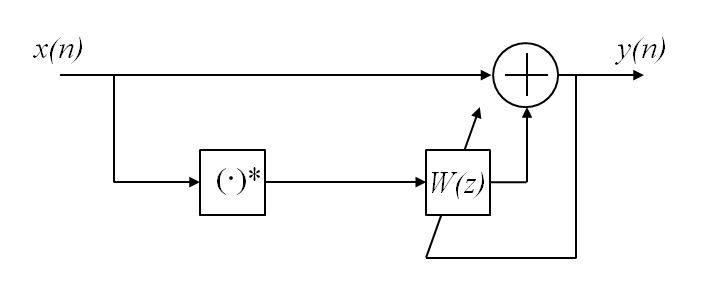
MATLAB also offers a function, comm.IQImbalanceCompensator, for this purpose. The compensated signal is expressed as $y(n) = x(n) + wx^*(n)$.

Block diagram of IQ imbalance compensator (from Matlab documentation)
Conclusion
IQ imbalance is a significant impairment in zero-IF transceivers, resulting in distorted constellations and image signals that degrade system performance. Understanding its causes, modeling it mathematically, and employing effective compensation techniques are essential for mitigating its impact, particularly in advanced communication systems.
This article marks the end of my series on RF impairments. I hope you have gained some understanding of these impairments and their impact on communication systems. I found them essential when applying for an RF system integration position, and I hope they will be useful for you as well. If you have any questions or suggestions, feel free to reach out to me. Thank you for reading!
Comments powered by Disqus.